
The RX17-2 and the RX18.
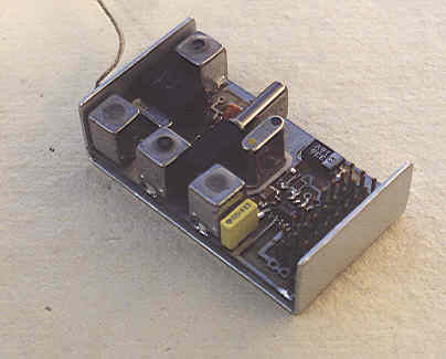
Below the finished RX17-2
The RX17-2 and the RX18 are two very good receivers
that you can easily build.
These receivers show now characteristics such as it
appears difficult to us to do better ... in dimensions which
are imposed to us by our embarked systems.
Let us review the characteristics of these two receivers:
a) They are of the type double change of
frequency.
That guarantees a total immunity against image frequency, Achilles'
heel of the receivers with simple changer.
b) They are provided with a 10.7
MHz quartz filter Such a filter, much more selective than its ceramic
equivalent, ensures an intermodulation minimum at the level of the second
change of frequency, thus removing badly " ghost " receptions. The
selectivity of filter 10.7 MHz
also
contributes to a good rejection of image frequency
c) They have an input HF stage . What allows a very good sensitivity,
d) This stage HF is provided with an Automatic Gain Control, said AGC. This
addition is recent and only justifies with it this new description. The AGC allows
to have a sensitive receiver when the signal is weak and to strongly reduce this
sensitivity when the signal is strong. When one remembers that the misdeeds of
intermodulation appear when strong signals enter simultaneously in first mixer, one
guesses that the AGC strongly improves the total behavior of the receiver at the time of
such situations, very frequent on the ground, models generally evolving/moving near of
several transmitters in service.
To reduce the sensitivity of the receiver is also an excellent manner of improving its
apparent selectivity. Indeed, when a receiver is saturated by an excessive signal, the
quartz filters or ceramics " are overflowed " and let it pass, even if it is on
an adjacent channel. To reduce the amplitude of HF signals BEFORE filtering them is thus
an excellent initiative !
e) Our two receivers are entirely carried out in Components Assembled on the Surface
(SMD). It results from it :
- a very higher reliability. Only one example : It is enough to
examine a traditional resistance. It is a resistive stick at the ends of which two cups
metal cups are crimped onto which two wires, welded electrically that you in addition weld
in your assembly. Count! That made 2x3 = 6 electric criticals junctions and sensitive to
the vibrations. Equivalent SMD is a resistive plate with metallized ends and welded on
the board. Therefore 2 junctions only. Moreover this light component , is
fitted on the epoxy board : It cannot vibrate.
- the smaller active components have internal connections much shorter
and therefore, less parasitic inductances and capacities. In other words, they are more
powerful!
1. The Diagram.

You initially finds in fig. 1 the simplified diagram of the assembly. You see the HF amplifier T1, two mixers delivering one the 10.7 MHz, the other the 455 kHz then the saturated amplifier with the 455 kHz. Finally the FM demodulator and the output comparator which provides a rectangular signal to the logic of decoding. Let us note also the AGC chain with transistors T2 and T3 for gain control of T1 T1.
The diagram of detail of Fig.2 gives additional precise details: The signal HF collected by the antenna is amplified by T1, framed reel S of agreement L1 and L2. To vary the profit of T1, it is enough to vary its supply voltage. Here it passes from 4v to 0V, the varying profit of +10 dB with - 10 dB, is 20 dB on the whole. It is far from bebeing negligible! All the remainder of the assembly is integrated in a MC3362 from MOTOROLA. To notice quartz QZ1 ensuring the local oscillation of first mixer. Its frequency is of Freq/reçue- 10700 in kHz, so as to come out of the 10.7 MHz, filtered by a XF106 of KVG. Applied to second mixer with its quartz of 10245 kHz, we obtain from the 455 kHz, filtered by a traditional CFW455. The 455 kHz is treated in-house by an amplifier on 6 floors which supplies a discriminator FM granted by L4. This amplifier delivers at the same time a D.C. current proportional to the intensity of the received field. (RSSI). This current is amplified by T2 and T3 and allows the control of the profit of T1.
Formatted rectangular by an internal comparator, the demodulated signal, present at the point " test BF " is sent towards a very traditional decoder: A shift register 8 bits realized with one 4015, solution to which we are faithful since many years. Let us note finally the regulator which fixes the tension D E electronics at + 4.2V. It is about a circuit with weak tension of waste and ridiculous internal consumption
2. REALIZATION
The RX17-2 wants to be subminiature. For that purpose, we use quartz out of case HC45, without support. According to the manner of assembling it, the RX17 measurement either 27x32x23 mm or 32x38x16 mm. See photographs. In both cases, volume is of 19.5 Cm3 and the weight of 22 G, out of case aluminum of 6/10, without particular precaution. For these two versions, it is possible to come out the connectors, either with the square of the circuits, or in the prolongation. See photographs. This second provision makes it possible to have a receiver of 16mm overall thickness, which facilitates its installation in the narrowest cells. For this provision, an additional plate, envisaged in the layout of the circuit, is to be welded onto the line of the barbs " signal ". The junction being done only by the weldings, without plug wire.
The RX18 is a mono-printed board version of the RX17. It thus has same surface 31x51 mm, but with a thickness half. Using ordinary quartz, the 10245 kHz welded and QZ1 onto support, it is a little less expensive than the RX17. It measures overall 32x52x18 mm and weights 30 g. It is thus a receiver which is appropriate perfectly for the majority of the installations. The absence of connection by wire between receiver and decoder accroit reliability. As for the RX17, the connectors assemble themselves either to the square, or parallel to U principal circuit.
a) Cases.
To make out of aluminum of 6/10 for the RX17 and the lid of the RX18 whose bottom is into 8/10. Work to be made carefully to have a good result. Decorative Scotchcal is available near the author.
Below the finished RX18
a) Printed circuits.
To order from the author
c) Installation of the components.
See the figures for the RX17- 2
and for the RX18.
d) Setting in service and adjustments.
See note.